Before blaming multicast, check that the hosts can ping each other.
1. Why I did this lab
Hmm… There isn’t a complete reason why I’m learning multicast. I just realized that if I want to pursue a career in FinTech, I must be very familiar with multicast. We learned it during the CCNA, CCNP, and CCIE courses, but if you don’t use it often in real-world work, you’ll probably forget most of the concepts.
I wanted to brush up on multicast, so back to the simplest setup I could think of. One exchange sends a feed, two feed handlers want it, and all three hosts sit on the same LAN. Before getting into PIM again, I wanted to see what the sender actually puts on the wire and what each receiver has to do to get the data.
2. Lab environment and topology
I used three Alpine hosts and one unmanaged switch in CML. The hosts take 512 MiB each, so that’s 1.5 GiB for the three guests. Four nodes fit easily within my CML Personal limit. Alpine already had iPerf 2 and tcpdump, so the setup was pretty quick.
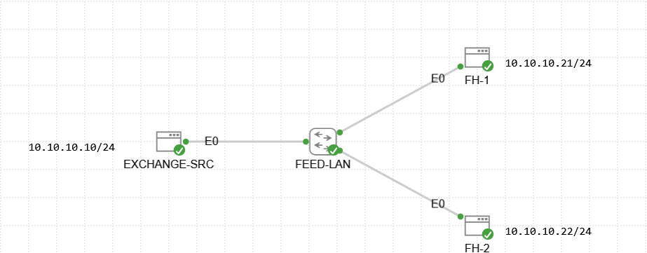 Figure 0. Lab topology.
Put all three interfaces in 10.10.10.0/24 and added ip route replace 224.0.0.0/4 dev eth0 inside the lab. The addresses in the diagram are enough to reproduce the setup. The channel I made up for this test uses source 10.10.10.10, group 239.10.10.1, and UDP destination port 5000.
3. Get unicast working first
Pinged .21 and .22 from the source first. Make sure unicast can reachable is the basic of the basic.
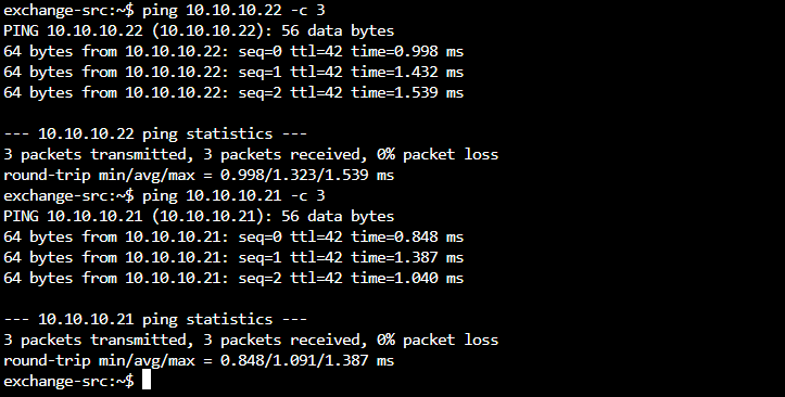 Figure 1. A little ping test.
Then started a UDP listener on FH-1 and sent 15 seconds of traffic directly to it. Pretty standard stuff, but now I have a baseline if the multicast test gives me nothing.
# FH-1
iperf -s -u -B 10.10.10.21 -p 5000 -i 1

# EXCHANGE-SRC
iperf -c 10.10.10.21 -u -B 10.10.10.10 -p 5000 -b 64k -l 256 -t 15
 Figure 2. Sender sent the UPD traffic to a unicast address.
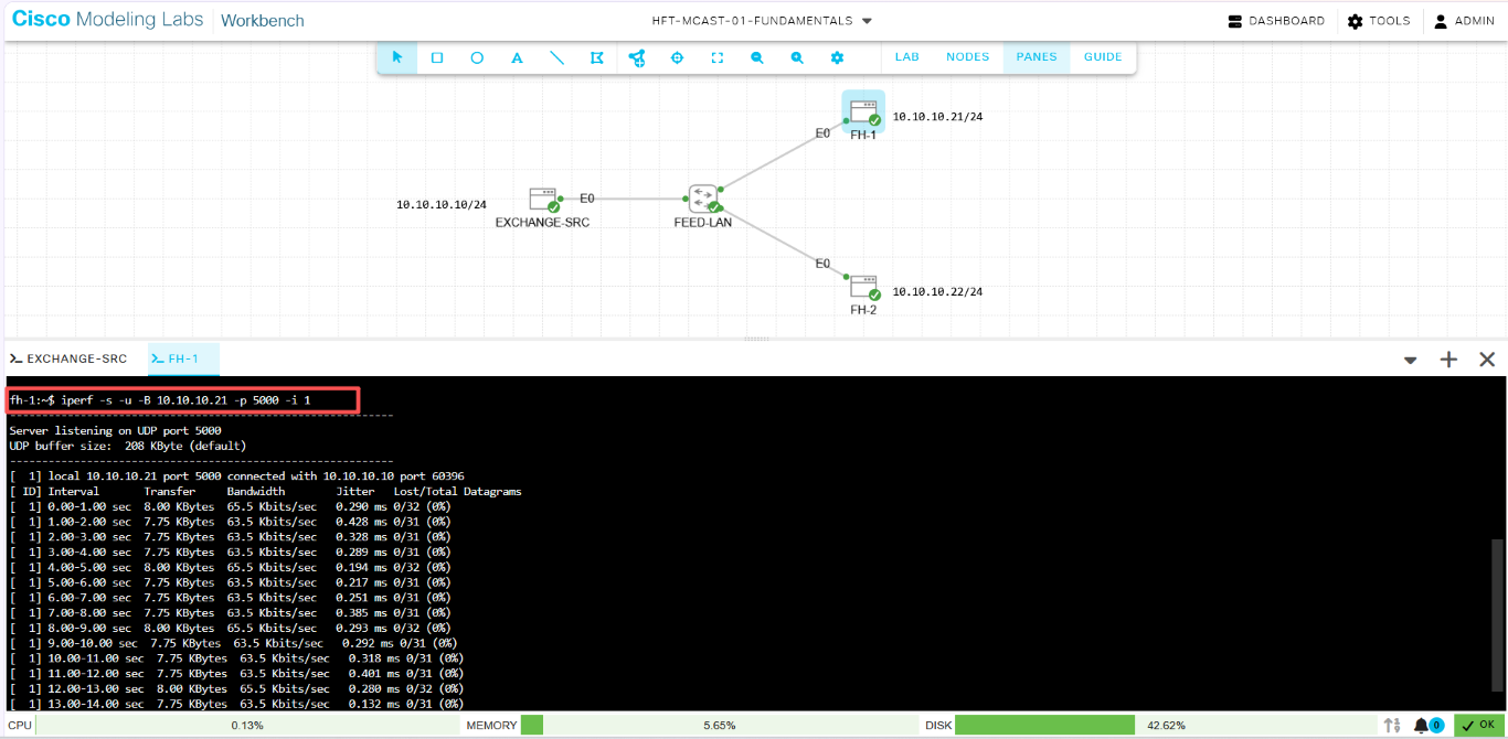 Figure 3. Receiver report traffic come from Sender’s address.
4. Send the same feed to both hosts
I stopped the unicast listener with Ctrl+C, then started the multicast listener on both hosts. The publisher sends to the group this time. Look at the sender command and see if you can find either feed handler’s IP in it.
# FH-1 and FH-2, in separate consoles
iperf -s -u -B 239.10.10.1 -p 5000 -i 1

# EXCHANGE-SRC
iperf -c 239.10.10.1 -u -B 10.10.10.10 -p 5000 -b 64k -l 256 -t 30 -T 1
The sender targets 239.10.10.1:5000, and the switch forwards a copy onto each receiver link in this setup. I kept the feed at 64 kbit/s. A few packets are enough to see what’s going on.
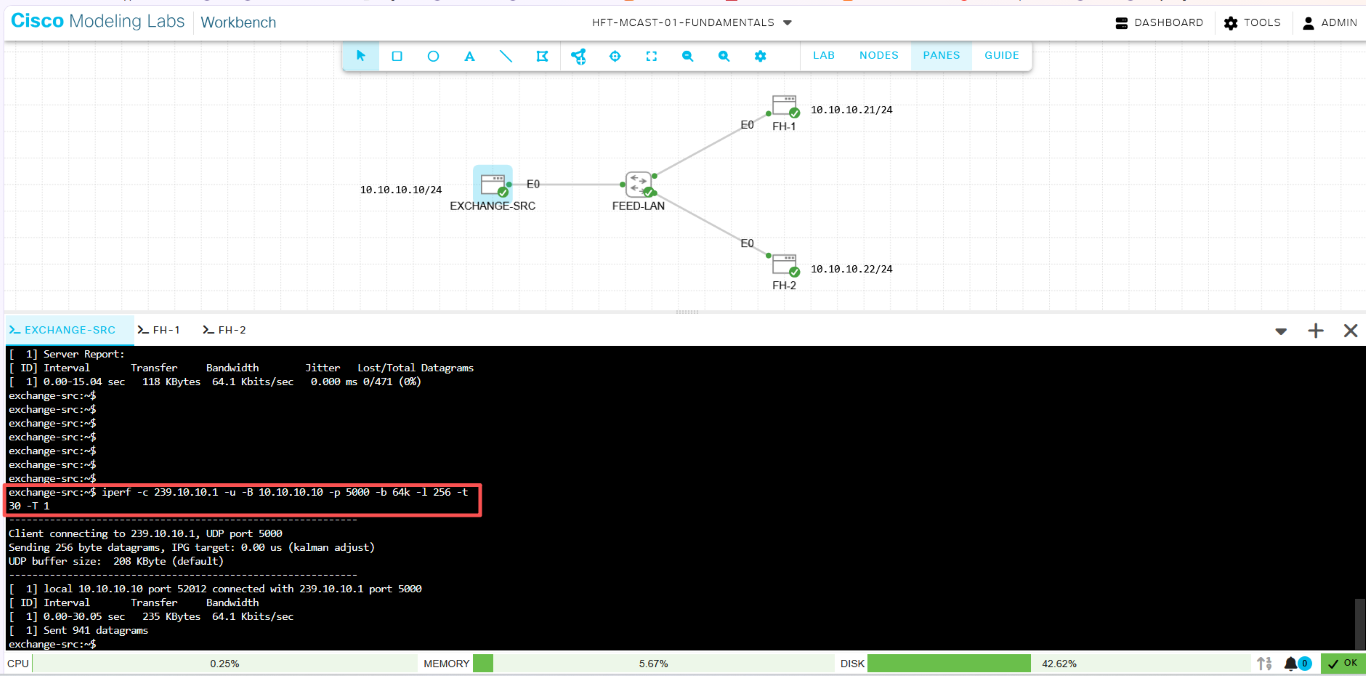 Figure 4. Sender sent the UPD traffic to a multicast address.
Both receivers can report traffic from that one stream :
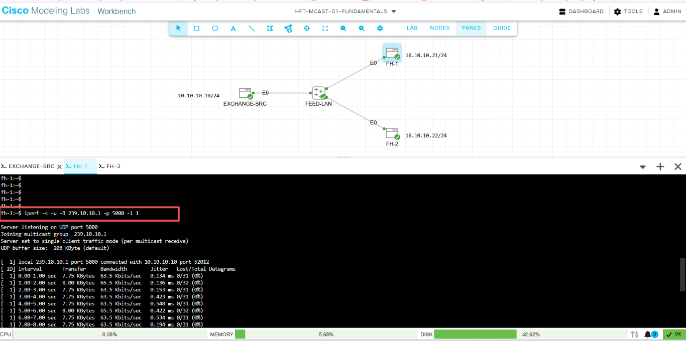 Figure 5. Receiver FH-1 report traffic come from multicast’s address.
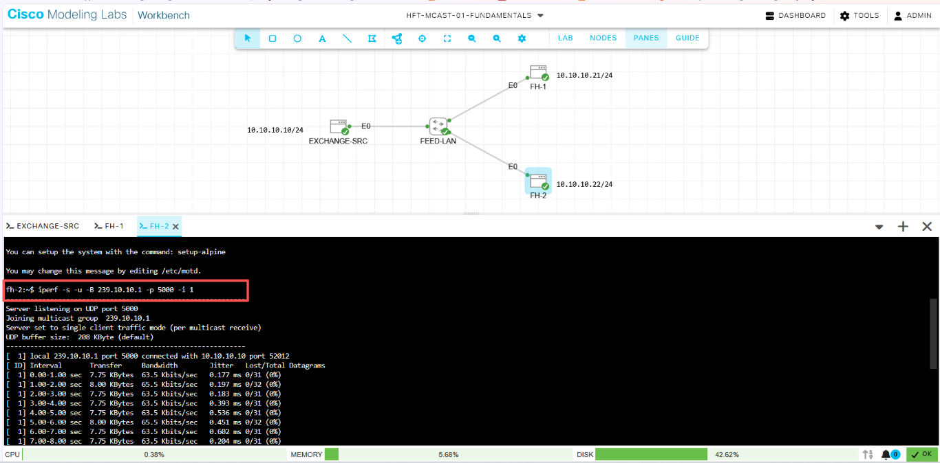 Figure 6. Receiver FH-2 report traffic come from multicast’s address.
5. Take a look at the packet
I ran this on a receiver while the source was sending. If you’re following along in CML, you can also capture the link between the source and the switch.
tcpdump -ni eth0 -e -vv -c 10 'udp and dst host 239.10.10.1 and dst port 5000'
The source IP is .10, the destination IP is 239.10.10.1, and 5000 is the UDP destination port. Look one layer down and the destination MAC is 01:00:5e:0a:0a:01.
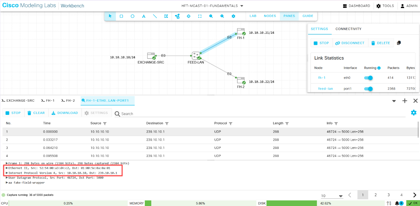 Figure 7. The packet capture detail.
Here’s the bit I had to work out again. What MAC does 239.138.10.1 map to? Same one. The mapping only uses the low 23 bits of the group address. The bit that changes between 10 and 138 in the second octet is outside those 23 bits. When filter a capture for a specific feed, check the destination IP as well as the MAC.
Think about it: can a market data packet with a TTL of 1 reach a receiver within the same VLAN? Can it traverse a normal router?
Sent the stream once with -T 1 and again with -T 16. Compare the two captures and the TTL changes with the sender setting. Compare the two links within the same run and it stays the same. There’s only a Layer 2 switch in between.
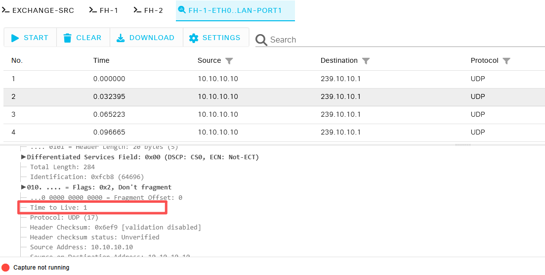 Figure 8. The packet capture detail with TTL 1.
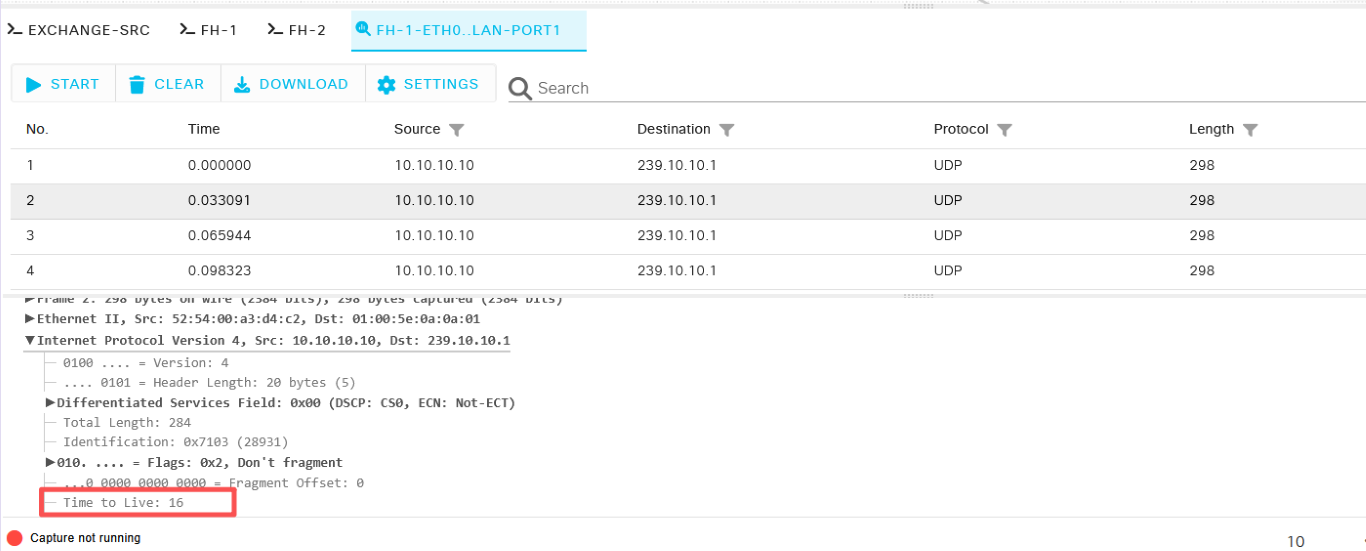 Figure 9. The packet capture detail with TTL 16.
Show answer
TTL limits how many Layer 3 hops a packet can traverse. Since Layer 2 switches do not decrement the TTL and routers do, a packet with a TTL of 1 cannot be routed any further.6. Same group, wrong port
I left FH-1 alone and restarted FH-2’s listener on 5001.
# FH-2, after stopping the listener on port 5000
iperf -s -u -B 239.10.10.1 -p 5001 -i 1
The source still sends to 5000.
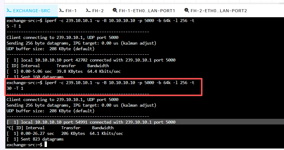 Figure 10. The Sender send the multicast traffic with port 5000.
The FH-2 link can have packets for the right group while its listener sits there waiting on 5001.
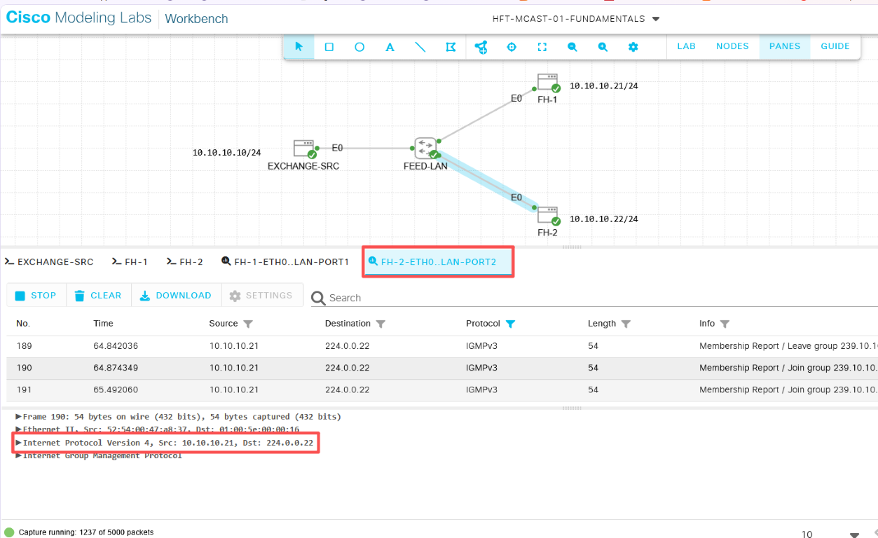 Figure 11. Capture in the li4nk between FH-2 and the switch.
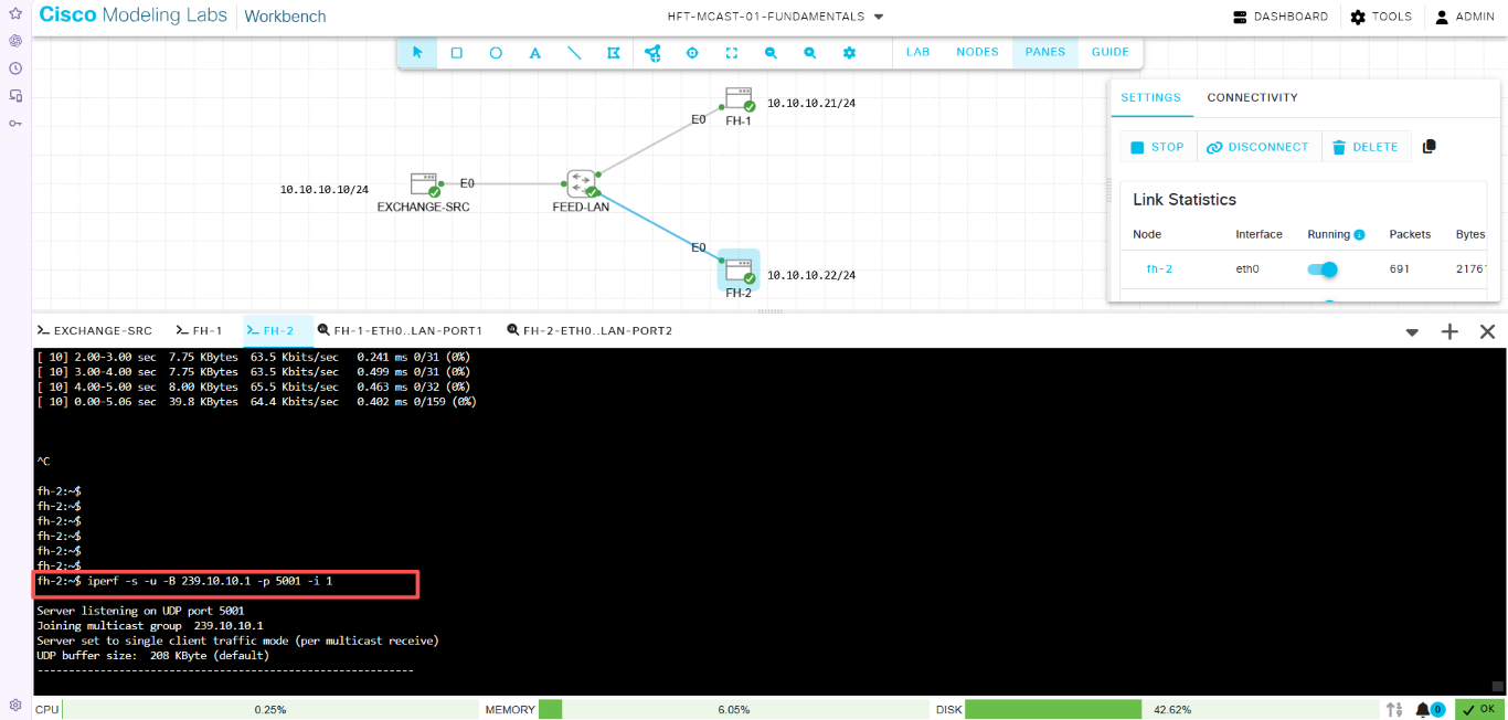 Figure 12. FH-2 waiting on port 5001.
That’s a quick way to separate group membership from UDP delivery. IGMP carries the group membership, and IGMPv3 can also carry source filters. The application still needs to listen on the right UDP port.
If FH-1 has market data and FH-2 goes quiet, I’d start by comparing the source, group, port, and interface on both sides. Then capture on the FH-2 link. If the right packets are there, check what the application joined and where it bound its socket. Also ask when the feed went quiet. A failure on startup and a failure just after a network change give me different places to start looking.
Next time I’ll use a switch with IGMP snooping and see which ports actually get a copy when only one feed handler joins.
iPerf 2 multicast command reference
